- Data Models in DBMS
- Entity Realtionship Model
- Relational Model:
- Hierarchical Model:
- Network Model:
- Constraints in DBMS:
Data Models in DBMS
Data Model gives us an idea that how the final system will look like after its complete implementation. It defines the data elements and the relationships between the data elements. Data Models are used to show how data is stored, connected, accessed and updated in the database management system. Here, we use a set of symbols and text to represent the information so that members of the organisation can communicate and understand it.
Entity Realtionship Model
An ER model describes the structure of a database with the help of a diagram, which is known as Entity Relationship Diagram (ER Diagram).An ER model is a design or blueprint of a database that can later be implemented as a database. An ER diagram shows the relationship among entity sets. An entity set is a group of similar entities and these entities can have attributes.
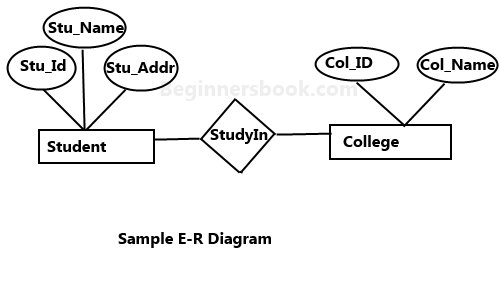
In above diagram,
- Rectangle———->Entity Sets
- Ellipses———->Attributes
- Diamonds———->Relationship Set
- Double Ellipses———->Multivalued Attributes
- Dashed Ellipses———->Derived Attributes
- Double Rectangles———->Weak Entity Sets
- Lines———->They link attributes to Entity Sets and Entity sets to Relationship Set
- Double Lines———->Total participation of an entity in a relationship set
3 components of ER-diagram:
1. Entity:
Entity is a real-world thing. It can be a person, place, or even a concept. Example: Teachers, Students, Course, Building, Department, etc are some of the entities of a School Management System.
Weak Entity:
- An entity that cannot be uniquely identified by its own attributes and relies on the relationship with other entity is called weak entity.
- The weak entity is represented by a double rectangle.
- For example, a bank account cannot be uniquely identified without knowing the bank to which the account belongs, so bank account is a weak entity.
2. Attribute:
An entity contains a real-world property called attribute. This is the characteristics of that attribute. Example: The entity teacher has the property like teacher id, salary, age, etc. 4 Types of Attributes:
Key Attribute:
- A key attribute can uniquely identify an entity from an entity set.
- For example, student roll number can uniquely identify a student from a set of students.
- Key attribute is represented by oval same as other attributes however the text of key attribute is underlined.
Composite Attribute:
- An attribute that is a combination of other attributes is known as composite attribute.
- For example, In student entity, the student address is a composite attribute as an address is composed of other attributes such as pin code, state, country.
Multivalued Attribute:
- An attribute that can hold multiple values is known as multivalued attribute.
- It is represented with double ovals in an ER Diagram.
- For example, A person can have more than one phone numbers so the phone number attribute is multivalued.
Derived Attribute:
- A derived attribute is one whose value is dynamic and derived from another attribute.
- It is represented by dashed oval in an ER Diagram.
- For example, A Person age is a derived attribute as it changes over time and can be derived from another attribute (Date of birth).
3. Relationship:
Relationship tells how two entities are related. Example: Teacher works for department.Here, “works for” is relationship.4 types of Relationship.
One to One:
- when single instance of one entity is associated with single instance of other entity then it is called one to one relationship.
- For example, a person has only one passport and a passport is given to one person.
One to Many:
- When a single instance of an entity is associated with more than one instances of another entity then it is called one to many relationship.
- For example, a customer can place many orders but a order cannot be placed by many customers.
Many to One:
- When a more than one instances of an entity is associated with single instance of another entity then it is called many to one relationship.
- For example, many students can study in a single college but a student cannot study in many colleges at the same time.
Many to Many:
- When more than one instances of an entity is associated with more than one instances of another entity then it is called many to many relationship.
- For example, a student can be assigned to many projects and a project can be assigned to many students.
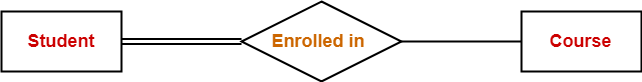
Total Participation:
- It specifies that each entity in the entity set must compulsorily participate in at least one relationship instance in that relationship set.
- Total participation(mandatory participation) is represented using a double line between the entity set and relationship set
- In Below figure,
- Double line between the entity set “Student” and relationship set “Enrolled in” signifies total participation.
- It specifies that each student must be enrolled in at least one course.
Partial Participation:
- It specifies that each entity in the entity set may or may not participate in the relationship instance in that relationship set.
- Partial participation(optional participation) is represented using a single line between the entity set and relationship set.
- In Below figure,
- Single line between the entity set “Course” and relationship set “Enrolled in” signifies partial participation.
- It specifies that there might exist some courses for which no enrollments are made.
DBMS Generalization:
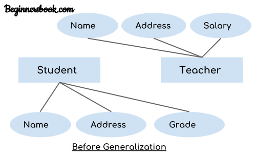
Generalisation is a process in which common attributes of more than one entities form new entity.This newly formed entity is called a generalized entity.Lets look with an example,
The ER diagram before generalization looks like this:
The ER diagram after generalization looks like this:
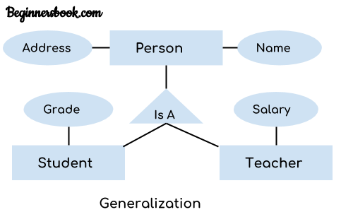
- NOTE:
- Generalization uses bottom-up approach where two or more lower level entities combine together to form a higher level new entity.
- The new generalized entity can further combine together with lower level entity to create a further higher level generalized entity.
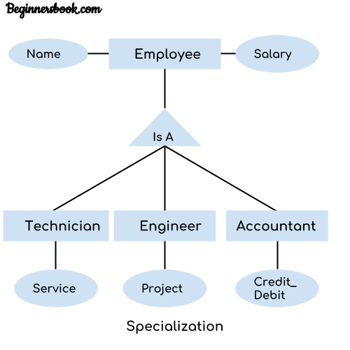
DBMS Specialization:
In specialization, an entity is divided into sub-entities based on their characteristics. It is a top-down approach where higher level entity is specialized into two or more lower level entities. For example, Consider an entity employee which can be further classified as sub-entities Technician, Engineer & Accountant because these sub entities have some distinguish attributes.
DBMS Aggregation:
Aggregation is a process in which a single entity alone is not able to make sense in a relationship so the relationship of two entities acts as one entity.
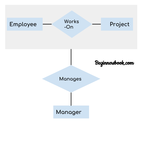
In real world example, we know Manager not only manages employee working under them but also project as well.In such scenario, if entity “Manager” makes “manages” relationship with either “Employee” or “Project” entity alone then it will not make any sense because he has to manage both.In these cases the relationship of two entities acts as one entity. In our example, the relationship “Works-On” between “Employee” & “Project” acts as one entity that has a relationship “Manages” with the entity “Manager”.
Relational Model:
In Relational Model, Data and relationships are represented by collection of inter-related tables.
- Each column in table represents attribute of an entity.
- Each row in table represents records(tuples).
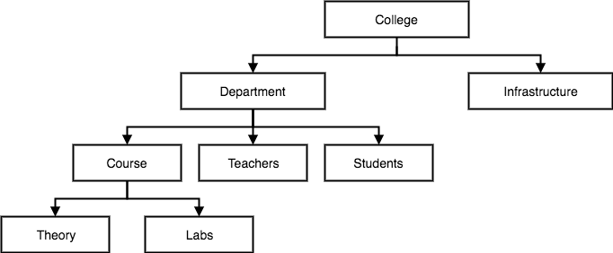
Hierarchical Model:
This database model organises data into a tree-like-structure, with a single root, to which all the other data is linked. The heirarchy starts from the Root data, and expands like a tree, adding child nodes to the parent nodes.
- Each child node has only single parent node.
- This model efficiently describes many real-world relationships like index of a book, recipes etc.
- The main drawback of this model is that, it can have only one to many relationships between nodes. for example, one department can have many courses, many professors and of-course many students
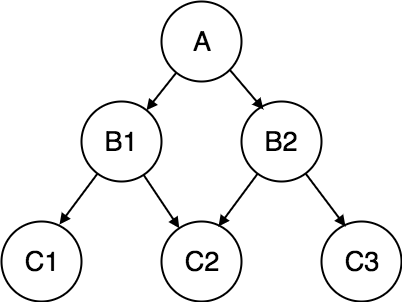
Network Model:
This is an extension of the Hierarchical model. In this model data is organised more like a graph, and are allowed to have more than one parent node.
- In this database model data is more related as more relationships are established in this database model. Also, as the data is more related, hence accessing the data is also easier and fast.
- This database model was used to map many-to-many data relationships.
- This was the most widely used database model, before Relational Model was introduced.
Constraints in DBMS:
constraints enforce limits to the data or type of the data that can be inserted/updated/deleted from a table.The whole purpose of constraints is to maintain the data integrity during an update/delete/insert into a table.
Types of Constraints:
NOT NULL:
- NOT NULL constraint makes sure that a column does not hold NULL value.
- When we don’t provide value for a particular column while inserting a record into a table, it takes NULL value by default.
UNIQUE:
- UNIQUE Constraint enforces a column or set of columns to have unique values.
- If a column has a unique constraint, it means that particular column cannot have duplicate values in a table.
DEFAULT:
- The DEFAULT constraint provides a default value to a column when there is no value provided while inserting a record into a table.
CHECK:
- This constraint is used for specifying range of values for a particular column of a table.
- When this constraint is being set on a column, it ensures that the specified column must have the value falling in the specified range.
Key Constraints:
PRIMARY KEY:
- Primary key uniquely identifies each record in a table.
- It must have unique values and cannot contain nulls.
FOREIGN KEY:
- Foreign keys are columns of the table that points to primary key of another table.
- They act as cross-reference between tables.
Domain Constraints:
- Each table has certain set of columns and each column allows a same type of data, based on its data type. The column does not accept values of any other data type.
- Domain constraints are user defined data type and we can define them like this:
- Domain Constraint = data type + Constraints (NOT NULL / UNIQUE / PRIMARY KEY / FOREIGN KEY / CHECK / DEFAULT)
Mapping Constraints:
- mapping constraints can be explained in terms of mapping cardinality.
- one to one, one to many, many to one, many to many.
Assuming, that a customer orders more than once, the below relation represents one to many relation.
CREATE TABLE Customer (
customer_id int PRIMARY KEY NOT NULL,
first_name varchar(20) NOT NULL UNIQUE,
last_name varchar(20) NOT NULL UNIQUE,
Age int NOT NULL check(Age>15),
Address varchar(20) Default "durgapur"
);

CREATE TABLE Order (
order_id int PRIMARY KEY NOT NULL,
customer_id int,
order_details varchar(50),
constraint fk_Customers foreign key (customer_id)
       references dbo.Customer
);